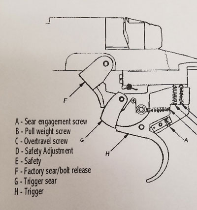
Installing the Savage Improved Extractor Kit

Posted in DIY, New Kit, Product Reviews, Savage on December 1st, 2017 by Preston Lewis

WARNING

Warning!

Before starting work on any firearm be sure that the firearm is clear. Do not touch the trigger until the firearm has been cleared. Inspect the chamber to ensure that it is clear of ammunition and that there is no ammunition positioned to be chambered. Do not keep live ammunition near your workspace. Once you have checked the firearm, check it again!

Tactical Works, Inc. takes no responsibility for the accuracy and/or safety of this “how to”.  This post is simply for your reading enjoyment. Before shooting any firearm have it inspected by a qualified gunsmith.


In this Do-It-Yourself Tutorial, we will be installing the Savage Improved Extractor Kit.

List of tools you need to accomplish this installation successfully.

  • Clean Workspace
  • Tweezers
  • 1/6″ punch
  • Small mallet
  • Small flathead screwdriver
  • Compressed air or canned air
  • 4″ piece of packing tape
  • Gun oil
  • Good set of eyes (joking but for real!)

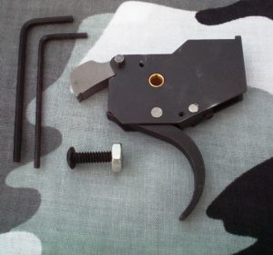
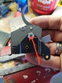
This kit consists of a modified extractor, larger extractor detent ball, and custom ejector and ejector spring.

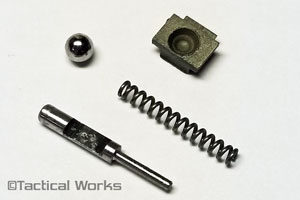
*Some of the installation pictures show the original kit parts. The new kit parts (pictured above) may look slightly different but the installation steps are the same.

Step 1: Remove the bolt from your rifle.

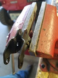
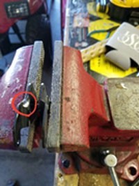
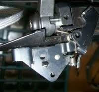
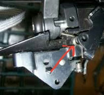
Step 2: In this step, we will be removing the OEM Extractor from the bolt head. Take your flathead screwdriver (make sure it is small enough to fit in the slot in front of the extractor) and place it flat against the extractor. With a small amount of pressure, push the extractor toward the outside of the bolt face as shown in Figure 2-1.  Make sure while you are pushing the extractor that you keep a hand over the bolt face because the detent ball underneath the extractor will shoot out if you’re not careful.  See Figure 2-2.

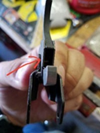
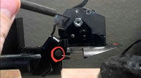
Step 3: Once the extractor is clear of the bolt and the detent ball is captured, use your tweezers to pull the spring out of the blind hole. See Figure 3.1. Lay the OEM extractor and detent ball on the piece of tape as shown in Figure 3.2. Lay the spring to the side as you will reuse it with the new extractor. Figure 3.3.

Step 4: Once the spring is removed from the blind hole, take your air compressor or canned air and blow the blind hole out to get any residual dirt, dust or grime out. Apply a few drops of gun oil into the hole as well as on the spring and place the spring back into the blind hole (either direction, doesn’t matter). See Figure 4.1. 

Step 5: Place the new (larger) detent ball on top of the spring. It should sit on the spring sticking out above the bolt face. See Figure 5.1. 

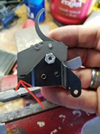
Step 6: In Figure 6.1, notice the new extractor plate. The detent ball indention faces the bolt and the extractor lip faces the inside of the bolt face.

Step 7: Slide the new extractor into the slots in the bolt head until it contacts the detent ball as shown in Figure 7.1. Use your small flathead screwdriver and carefully push the detent ball down below the surface of the bolt face and slide the extractor plate in over the detent ball simultaneously. You will hear it snap into place. See Figure 7.2.

Step 8: Look for the ejector pin hole on the opposite side of the bolt as the extractor. This pin only comes out one way and only goes in one way. You will see an inlet on the top of the bolt head. This is the side where you will insert your punch. See Figures 8.1 and 8.2 for pin removal direction. Use your 1/16″ punch and insert it into the hole. Lightly tap the pin out of the bolt head until the pin is clear of the bolt head. Cup your hand over the bolt face and pull the punch out in the opposite direction.

Note*** Be sure that you capture the ejector rod and spring when you extract the punch as it is under pressure and will projectile if your hand is not over the face of the bolt.


Step 9:  Again, use your air compressor or canned air to blow out the ejector rod hole making sure to get any trash or sand out. Apply a few drops of gun oil into the hole and the new ejector spring as shown in Figure 9.1.

Step 10: Install the new ejector spring onto the new ejector rod. If you look at the ejector rod (as shown in Figure 10.1) there is a slot cut out on one side of the rod. Position the “cutout” facing toward the small extractor retention pin. Once you have the cutout in the ejector positioned correctly toward the pin, insert the ejector and spring into the blind hole.

Step 11: This next step is a little tricky…. Use your thumb to depress the ejector into the hole while simultaneously pushing the pin into the retention hole. Remember that the pin can only be inserted one way. See Figure 11.1.

Step 12: Once the pin is in place, push the ejector down a few times to make sure that is functions correctly and doesn’t bind. See Figure 12.1

Step 13: Install the bolt back into the action and cycle it forward and back. Hand feed an EMPTY case into the chamber and close the bolt. Cycle the bolt. Cycle the bolt rearward and make sure that the case ejects and kicks away from the gun. If this is successful, YOU ARE FINISHED!

**Note: Sometimes with installation you will find your bolt is hard to close. With the new parts being all stainless steel they are stiffer and may need some help mating up and breaking in. If you experience this problem you will need to place an EMPTY CASE in the chamber and slam your bolt. You may have to work your bolt to loosen it and may need to cycle it as above several times (sometimes upwards of 100 times). Then you should be good to go. As always just call or email us with any questions or concerns.

The Savage Improved Extractor Kit is a great upgrade to your Savage 10/110 and Savage Axis rifle. With this kit, you won’t have to worry about hung cases or failure to extract anymore. And it will kick the cases further away from the gun. 

You’ll be glad you spent the time to install this kit. It really adds a piece of mind knowing that your rifle is going to eject without a doubt whenever, wherever.

As always,

See you on the range!!

Preston

Tags: , ,

Installing the SSS Savage Competition Trigger

Posted in DIY, Savage on November 10th, 2017 by Preston Lewis


WARNING

Warning!

Before starting work on any firearm be sure that the firearm is clear. Do not touch the trigger until the firearm has been cleared. Inspect the chamber to ensure that it is clear of ammunition and that there is no ammunition positioned to be chambered. Do not keep live ammunition near your workspace. Once you have checked the firearm, check it again!

Tactical Works, Inc. takes no responsibility for the accuracy and/or safety of this “how to”.  This post is simply for your reading enjoyment. Before shooting any firearm have it inspected by a qualified gun smith.

Installing the SSS Savage Competition Trigger

SSS Savage Competition Trigger

SSS Savage Competition Trigger

In this DIY tutorial, we will be installing a Sharp Shooter Supply Competition trigger in a Savage Model 10 FCP-SR. This trigger is a great value and will take your rifle and accuracy to the next level. The SSS Competition Trigger has an adjustable pull range from 2 pounds to 12 ounces. It also comes with installation instructions as well as allen key wrenches. In order to have a successful trigger install, below are a list of tools needed.

  • Dremel Tool with a diamond dremel bit
  • Vise
  • Set of Allen Wrenches for stock or chassis removal
  • 1/8” drift punch to remove the main trigger frame pin
  • Small pair of Needle Nose Pliers to re-install the bolt release spring
  • Blue Loctite
  • Torque Wrench to reinstall the stock or chassis

Before you start, MAKE SURE YOUR GUN IS CLEAR AND UNLOADED. I cannot stress this enough. Safety First!!!

Step 1- Remove the bolt from the action

Step 2- Remove the front and rear action screws. (On a stock, you will remove the forward screw and the screw in front of the trigger guard. On a chassis such as a Stealth/MDT LSS chassis, you will only have 2 screws, remove both of them.

Step 3- Place your barreled action on a flat surface with the trigger facing up.

Step 4- Take your 1/8” drift punch and remove the Main Trigger Frame Pin shown in Figure 4-1.

SSS Savage Competition Trigger Installation

Figure 4-1

Once this pin is removed, slide the whole assembly forward towards the muzzle and pull up. It will come right out. Remove the bolt release lever and spring shown in Figures 4-2 and 4-3 below.

SSS Savage Competition Trigger Installation

Figure 4-2

SSS Competition Trigger Installation

Figure 4-3

Step 5- Carefully remove the “C” Clip on the side of the Accutrigger and pull the trigger pin out. Pull the entire trigger free of the frame and lay it to the side.

Step 6- Take the main trigger frame and put it in your vise so you will have a steady working surface as shown in Figure 6-1. (Only for Accutrigger Models will you have to modify the main trigger frame. Pre-2004 Savages have a different trigger frame that does not need to be modified.)

SSS Savage Competition Trigger Installation

Figure 6-1

Step 7- With the diamond bit in your dremel tool, carefully grind a slot into main trigger frame to allow clearance for the stud on the SSS trigger. (Looking at the frame from the front with the holes facing up you will be grinding the left side) As shown in Figures 7-1 and 7-2

SSS Savage Competition Trigger Installation

Figure 7-1

SSS Savage Competition Trigger Installation

Figure 7-2

Step 8- Grind a little at a time and slide the SSS Competition trigger into the frame until the frame sits right against the new trigger housing as shown in Figure 8-1. (You don’t want anything binding as your trigger will not function properly if anything is smashed.)

SSS Savage Competition Trigger Installation

Figure 8-1

Step 9- Once your new SSS trigger will sit perfect in your trigger frame with the two back feet shown in Figures 9-1 and 9-2 sitting on top of the trigger frame and the screw holes (frame and trigger holes) lined up perfectly, insert the provided machine screw through the hole (doesn’t matter through which side) and thread the provided nut onto the screw on the opposite side. Tighten the screw with the provided allen key until it is snug. DO NOT TORQUE THE NUT DOWN!! Apply a small amount of blue LOCTITE in the middle of the nut being careful not to get any into the trigger.Wipe off excess if needed.

SSS Savage Competition Trigger Installation

Figure 9-1

SSS Savage Competition Trigger Installation

Figure 9-2

Step 10- Once the SSS Trigger is installed in the main trigger frame, place the lip on the back of the frame into the slot in the rear of the action.

Step 11- Re-install the bolt release lever the way you took it off as shown in Figure 11-1 below.

SSS Savage Competition Trigger Installation

Figure 11-1

Step 12- Slide a small allen wrench through the holes of the bolt stop lever, main trigger frame and action as shown in Figure 12-1 allowing all of the components to line up correctly.

SSS Savage Competition Trigger Installation

Figure 12-1

Step 13- Install the bolt release lever spring with the small pair of needle nose pliers and push your allen wrench through the spring and all the way through the bolt release.

Step 14- Take your main trigger frame pin and slowly push it through the hole on the spring side pushing the allen key out. (Exactly the opposite way you inserted the allen key.) This step may take some fooling with but take your time and you will get it. See Figure 14-1. (Main trigger frame pin re-installed)

SSS Savage Competition Trigger Installation

Figure 14-1

Step- 15- Slide your safety tab to the rear  in the “Safe Position”. Use the smallest provided allen key to adjust “Screw D” clockwise until it touches the safety bar. (You can see it under the trigger housing). Once it is touching the safety bar, back it off 1/8 of a turn counter-clockwise. Install your bolt and “cock the gun” and pull the trigger and make sure IT WILL NOT FIRE WITH THE SAFETY ON!! If it does fire with the safety on, turn the screw clockwise until it won’t, making sure that your safety tab slides back and forth freely without binding.

SSS Savage Competition Trigger Installation

Figure 15-1

Step 16- “Screw C” is your Overtravel Screw. This screw will set your desired over travel. Turning the screw clockwise reduces the overtravel and counter-clockwise increases over travel. (If this screw is adjusted in all the way clockwise, it will not allow the trigger sear to engage.If this happens, turn the screw counter-clockwise until the sear will engage the trigger.)

Step 17- “Screw A” is the Sear engagement adjustment screw. A majority of your pull weight will be associated with this screw. This screw comes set from the factory for minimum sear engagement. It is advised to adjust this screw no more than one turn clockwise to reduce sear engagement, if you adjust this screw counter-clockwise, it will increase your trigger pull weight. Reducing the sear engagement introduces the risk of a slam fire or accidental sear disengagement.

Step 18- “Screw B” is your Trigger Pull Weight adjustment. You can set this screw where you so desire. Turning the screw clockwise increases your pull weight and turning it counter-clockwise reduces the pull weight.

Step 19- Once your trigger is adjusted to your preference, cycle the bolt no less than 100 times making sure you have no slam fires or unintentional sear disengagements. Also make sure your safety engages as well. SAFETY FIRST!!!!!!!!!!!!

Step 20- Once you’ve deemed your rifle “SAFE”, carefully lay the barreled action back into the stock or chassis. If you have a Savage Accustock, you will not have to modify the trigger guard or stock when reinstalling. If you have a Savage Stealth or MDT LSS chassis, you will have to open up the trigger hole about a ¼” forward to clear the new trigger housing. Your dremel with the same bit will do this easily.

Step 21- Once your action is sitting in your stock or chassis with no interference, apply a liberal amount of blue Loctite to the ends of the action screws. Thread the action screws into the actions and hand tighten them. With your torque wrench, tighten the rear action screw to 60 inch pounds and same for the front action screw. Once both screws are tightened to 60 inch pounds, tighten the rear action screw to 65 inch pounds.

You can, at any time, reinstall the Savage accutrigger. This modification isn’t permanent.

YOU’RE DONE!!!

Trigger Install Complete

Trigger Install Complete

Trigger Install Complete

Trigger Install Complete

This install is well worth the finished product, I promise you!!!

As always, see you at the range.

Project Savage: Choate Tactical Stock Installation

Posted in DIY, Project Savage, Savage, Tactical Works Home on July 7th, 2014 by Team TW

Savage Choate Tactical Stock


One of the upgrades that many shooters leverage is an upgraded aftermarket stock.  In a previous post we detailed the feature’s that this shooter is looking for which are drop-in-fit, full length bedding block, pistol grip,  free-floating barrel, immediately available, and not too expensive.  The Choate Tactical Stock fit the bill and the decision was made.

The rifle is a Savage 10 Hog Hunter in .223.  The Hog Hunter ships with an economical stock better known as the “Tupperware” stock.  The stock does have bedded pillars but is too flexible for reliable repeatable groups.    Some Savage rifles have the Accustock which will have three action screws.  The Savage Target Actions will also have three actions screws.  The Hog Hunter has two action screws.  This installation will focus on Savage actions that have two screws however we will try to address the three screws actions where we can.

Read more »

Bi-pod Lock Lever Installation

Posted in DIY, Tactical Works Home, Uncategorized on June 3rd, 2013 by Team TW


Swivel Bipods are almost necessary for accurate repeatable long-range precision shots.  Depending on theory, many suggest that the weapon should be able to swivel with a little force however should “stick” in the desired position requiring zero muscle or effort to hold the weapon in place.  The OEM Harris Swivel bipod does allow for tightening the tension on the swivel mechanism however it is a small wheel nut and it’s difficult to get the proper adjustment.  With a Bipod Lever Lock the operator can quickly and easily adjust the tension on the bipod without coming off the weapon system. The Bipod Lever Lock also allows for a more precise adjustment than does the OEM wheel nut.

Read more »

Tags:

Project Savage: Rear Sight Removal

Posted in DIY, Project Savage, Tactical Works Home, Uncategorized on May 3rd, 2013 by Team TW

Project Savage 11 Hog Hunter Sight Removal

The Savage Hog Hunter is factory shipped with iron sights for short range shots.   One option was to keep the iron sights as backup in the case of an optic failure however because this rifle is being built primarily as a training platform, there is no need for the irons.  Additionally, the OEM irons are somewhat entry level and removal is straightforward so they will be removed.
Read more »

Project Savage: Front Sight Removal

Posted in DIY, Project Savage, Tactical Works Home on April 26th, 2013 by Team TW

Project Savage 11 Hog Hunter Sight Removal

The Savage Hog Hunter is factory shipped with iron sights for short range shots.   One option was to keep the iron sights as backup in the case of an optic failure however because this rifle is being built primarily as a training platform, there is no need for the irons.  Additionally, the OEM irons are somewhat entry level and removal is straightforward so they will be removed.
Read more »

CDI/Choate Tactical Package Installation

Posted in CDI, Choate, DIY, Savage on September 22nd, 2011 by Team TW
CDI Precision Savage Bottom Metal

CDI Precision Savage Bottom Metal

We have been offering CDI Precision Gunworks Bottom Metal and Choate’s Tactical Stock for a while now. One of the top questions that we have been receiving is, “Can I buy the Choate stock and have you inlet it for the CDI bottom metal”? You asked and we have delivered!  We now offer our Choate Tactical stocks already inletted for the CDI bottom metal.

Read more »

Tags: , ,

Installation of the RAR

Posted in Accu-Shot, Choate, DIY, Tactical Works Home on February 14th, 2011 by Team TW

Choate Tactical Stock RAR

Choate Tactical Stock RAR and AccuShot PRS Monopod

Installation or a RAR (rear affixed rail) on a Choate Tactical Stock to allow for mounting picatinny rail mounted accessories such as a sling mount or a AccuShot PRM (precision rail mount) Monopod.

Read more »

Molding a Karsten Cheek Rest

Posted in DIY, Karsten Adjustable Cheek Rest, Tactical Works Home on January 18th, 2011 by Team TW
Karsten Kydex Cheek Rest

Molding a Karsten Cheek Rest to a Choate Tactical Stock

 Molding a Karsten Cheek Rest for a better fit. Karsten’s Cheek Rest “out of the box” is usually a perfect fit for most stocks. In some cases however, the “out of the box” cheek rest may be a little too wide or a little too narrow for a perfect fit. In those cases the cheek rest can be molded for a better fit.

Read more »

Tags: , , ,

Installing the Badger Ordnance M5 Trigger Guard & Choate Tactical Stock

Posted in DIY on January 14th, 2011 by Team TW

WARNING

Warning!

Before starting work on any firearm be sure that the firearm is clear. Do not touch the trigger until the firearm has been cleared. Inspect the chamber to ensure that it is clear of ammunition and that there is no ammunition positioned to be chambered. Do not keep live ammunition near your workspace. Once you have checked the firearm, check it again!

Tactical Works, Inc. takes no responsibility for the accuracy and/or safety of this “how to”.  This post is simply for your reading enjoyment. Before shooting any firearm have it inspected by a qualified gun smith.

Installing the Badger Ordnance M5 Trigger Guard with the Choate Tactical Stock

Badger M5 Choate Installation

Until now installing a dropbox magazine on your Remington 700 ADL or BDL required sourcing all of the parts and then sending your stock off to a gunsmith to be inletted. This required paying to ship your stock, waiting, and then paying to have the stock sent back. Now you can order a complete solution that is bolt-on, out-of-the-box, and can be assembled in less than an hour without special tools.

Parts:

  • Choate Tactical Stock Inletted for the Badger Ordnance M5 Trigger Guard.
  • Badger Ordnance M5 Trigger Guard Kit. (kit includes trigger guard, 5-shot magazine, 2 #3o Torx screws, 2 aluminum pillars)

Badger M5 Choate Installation

Tools:

  • 5/32 Hex/Allan Key
  • #30-Torx Driver and/or Socket
  • Calibrated Torque Wrench

Time:

Less than one-hour.

Remove all optics and accessories that might get in the way or be damaged during installation. Our subject rifle is a Remington 700 PSS. The original floor plate has been replaced with a MagXtender however, installation is the same for rifles that  have the OEM floor plate.

Badger M5 Choate Installation

Remove the Bolt from the rifle. Press the Bolt Release button which is located in the top of the trigger guard in front of the trigger.

Badger M5 Choate Installation

While the Bolt Release button is depressed, slide the bolt all the way back until the bolt is free of the action. Set the bolt aside until ready to reassemble.

Badger M5 Choate Installation
Use a 5/32″ Hex key to remove the two trigger guard screws.
Badger M5 Choate Installation

Badger M5 Choate Installation

Once both action screws are removed, the trigger guard will be free from the original stock and barreled action. Gently pull the trigger guard from the stock while supporting the barreled action. Make sure the barreled action is supported or it will drop free from the stock and can be damaged.

Badger M5 Choate Installation

Remove the trigger guard and the internal magazine box from the stock. The entire trigger guard and internal magazine will not be reused. Remove parts from the workspace for the remainder of the installation. Remove the barreled action from the stock and place it out of the way as well. The stock will not be used again for this project.

Badger M5 Choate Installation

Gather the new Choate Tactical Stock, the Badger M5 Trigger Guard, and both of the supplied T-30 Action Screws and place them on your workspace. The supplied Badger Ordinance Pillars are not used for this application. This is due to the full length aluminum bedding block used in the Choate Tactical Stock.

Badger M5 Choate Installation

Place the barreled action into the Choate Tactical Stock. Supporting the barreled action, turn the rifle over and insert the Badger Ordnance M5 Trigger Guard into the inlet stock. Insert the longer of the two #30-Torx action screws into the rear of the trigger guard. The shorter of the two #30-Torx action screws installs in the front of the trigger guard.

Badger M5 Choate Installation

To get the action screws started, thread them by hand to avoid damaging the threads on the action screws and more importantly the action. Once the action screws are started, slowly and carefully tighten them equally taking time to make sure neither of the action screws are too long. If one or both of the action screws are too long you will need to either trim the supplied action screws or purchase new shorter screws. The action screws are a 7/28 thread that can be found at most chain hardware stores.

Badger M5 Choate Installation

When both action screws are snug and are the proper length to clear the bolt use a #30-Torx driver to torque them to 65 in-lbs. Caution! Failure to torque the action bolts with a calibrated Torx Driver may result in damage to the rifle! Per Badger, LocTite not needed.

Badger M5 Choate Installation

After installing the trigger guard double-check that the action screws will clear the bolt and install the bolt. Next insert the supplied Accuracy International 5-shot magazine into the Badger Trigger Guard. With the rifle unloaded cycle the bolt to make sure that the bolt cycles freely and does not hang up on the magazine.

Installation complete!